The CCTV systems have become an integral part of our homes, shops, offices, and businesses. If you want to monitor the entrance, exit, halls, parking, and any other space, you require a good CCTV system at key locations.
To install CCTV cameras at key points, you need a CCTV wiring diagram. The diagram will provide a layout to build the infrastructure. Without a well-thought-out diagram, you may miss important coverage areas.
The post guides readers about the CCTV Wiring Diagram for Home and Office. You will find here the diagram to connect DVRs/NVRs, power supply, cameras, and other accessories for your homes and offices.
It will also reveal to you how to avoid common mistakes in building the CCTV system. This way, you design a wiring system that works smoothly and securely.
CCTV Wiring Diagram for Home and Office
We will discuss this topic in detail here. We will also illustrate diagrams to ascertain various ways of wiring and installation systems in different setup conditions.
We will discuss here why a wiring diagram is required and how it helps in managing and understanding different CCTV systems.
Why Do We Need a Wiring Diagram?
A wiring diagram is your basic wiring structure. It gives you insight to connect your various CCTV devices and accessories. It specifically shows you the DVR/NVR connection with cameras, POEs, power supplies, and monitors.
Without a diagram, you may face issues like less suitable camera locations, video and power loss, and poor image quality.
A CCTV diagram for the home and office gives you the following benefits.
- Clear Perspective– You exactly know what you are doing.
- Reduces ‘Error Chances’– Since the structure is in your mind and hand, chances are low that you will make mistakes.
- Installation & Service becomes easier– If any problem crops up, you can easily manage because of the layout. Easy troubleshooting.
- System Expansion– System expansion in future becomes easier.
These are the overt and covert benefits of a CCTV diagram.
The Three Types of CCTV Systems
Basically, there are three kinds of CCTV systems we use for homes and offices. They are Analog systems, HD systems, and IP systems.
1- Analog CCTV Systems
- In this system, we use RG59 coaxial cables for audio and video transmission.
- Requires a DVR and analog CCTV cameras.
- Often, power is transferred through a separate power cable.
- This is an old CCTV system technology and is viable only for small and less sensitive locations.
2- AHD, HDCVI, & HDTVI Systems
- This system is an upgraded version of Analog systems. It has AHD, HDCVI and HDTVI versions.
- It also uses coaxial cable and power cable for wiring.
- The wiring system is almost the same, but the advantage is better image quality and footage, up to 4k.
3- IP CCTV System
- It is the latest and most modern CCTV system setup for homes and offices.
- The IP system uses the Ethernet cable or Cat6 wires.
- The Network Video Recorder (NVR) is connected to IP cameras, switches, and a monitor.
- Its advanced devices use PoE (Power over Ethernet) switches for data and power supply.
- This is the trendiest and best CCTV system for homes and offices. It can be used for large-scale projects.
What are the Important Factors in a CCTV Wiring Diagram?
A wiring diagram basically has the following essential factors.
- NVRs or DVRs
- CCTV Cameras- Analog, HD, or IP modes
- Power Supply- These include adapters, switches, PoEs, etc.
- CCTV Cables- They include RG59, Coaxial, Cat6, Power cable, Ethernet and Fiber Optics.
- Connectors– BNCs, AVs, RJ45, etc.
- Monitoring Screen- TVs and Monitors.
- Routers and Switches.
Now, we create diagrams for our homes and offices.
1- CCTV Wiring Diagram for Homes
We install CCTV in our homes for security and monitoring. Generally, these setups are for 4,8 or 16 cameras. We draw a diagram for Analog and HD Systems.
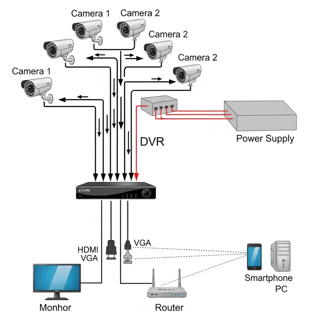
Wiring Diagram for Analog/HD Systems
Consider the following points.
- We use a coaxial cable and connect DVRs to it. All cameras require separate wiring up to the DVR.
- A separate power cable is required for each camera up to the power supply.
- Each camera wire is attached to the DVR through a BNC.
- The DVR is connected to a monitor through a VGA or HDMI cable.
- If we want to access the system remotely, we require a monitor. We connect the router and DVR through a LAN cable or Wifi.

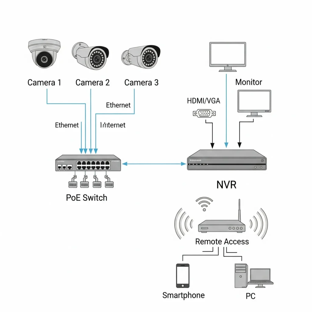
Wiring Diagram for IP Systems
- This system is connected to homes via an Ethernet or Cat6 cable.
- We require a port switch or PoE. It supplies power to the system and maintains the video transmission.
- We connect the PoE switch to the NVR through an Ethernet cable.
- A router is connected to the NVR for online and remote access to CCTV devices.
- The NVR is connected to the monitor for live streaming.

2- CCTV Wiring Diagram for Offices
The Analog/HD and IP systems for offices are shared below.
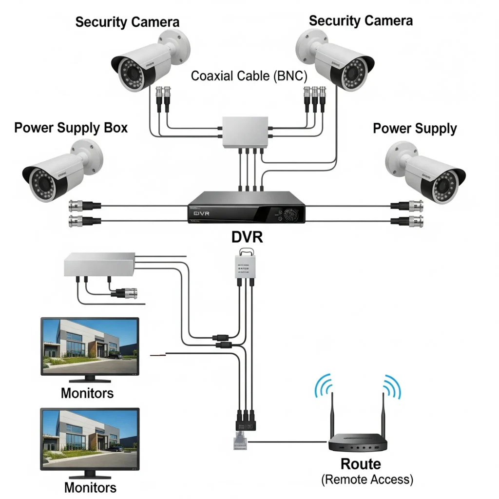
Wiring Diagram for Analog and HD Systems
- Uses coaxial cables, and all cables are connected to the DVR.
- All cameras are separately wired for video and power.
- A centralised power supply gives power to all cameras.
- A router is required for online live streaming and remote access on smartphones and monitors from anywhere in the world. Via a LAN Cable, the DVR and monitor are connected.
- The DVR is connected to the monitor or TV through a VGA or HDMI cable.

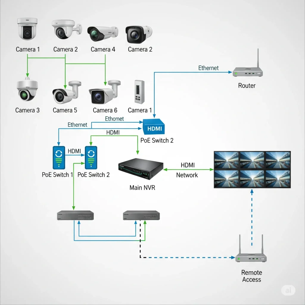
Wiring Diagram for IP Systems
- The NVR, IP Camera, PoE switch, and Router are required in this setup.
- The Cat6 or Ethernet cable is used for wiring.
- A PoE switch is installed location-wise. The IP camera wires are connected to the switch.
- An uplink Cat6 wire from the PoE is connected to the NVR. This way, cameras are connected to the NVR through the switch.
- The NVR is connected to the Monitor through an HDMI cable.
- The router is connected via a LAN or wifi for remote surveillance.

This way, these systems are connected for an office setup. Diagrams illustrate the methodology completely.
Kinds of Cables & Their Connections
1- Coaxial Cables– It is used in Analog and HD CCTV systems. Through it, videos can be transferred up to 50 meters. At the end, a BNC connector is joint to connect with the DVR.
2- Ethernet or Cat6 Cables– This cable is used in the installation of IP cameras. It can transfer videos up to 100 meters without the use of repeaters. The RJ45 connectors are required.
3- Fibre Optics– These cables are used for big projects spread across kilometres. Mostly factories, industries, institutions, and large-scale private and government projects are covered through this cable. Fibre optics has high bandwidth without any interference.
4- Power Cables– A power cable is a 2-core copper cable used for 12V DC.
How to Design a Diagram for CCTV Wiring Step-by-Step?
Follow these steps to smoothly design the layout.
Step 1– Do the inspection. Survey the site and decide the potential camera location.
Step 2- Mark every area where you are going to fix NVRs, DVRs, cameras, PoEs, power supplies, etc. Draw a diagram for it.
Step 3– Select the cable type required based on products and locations.
Step 4– Decide on the cabling part. How are you going to run cables? Through walls, ceilings, or conduits.
Step 5- This step is to make connectors (BNC or RJ45).
Step 6- Give power to the system via a PoE or power supply.
Step 7- Install DVRs or NVRs to connect all cameras.
Step 8– Test the system, its functions, and video quality. If any problem occurs, check the system step-by-step.
Avoid These Mistakes
- Avoid using low-quality wires and cables.
- Avoid laying CCTV cables and power cables parallel to each other.
- Don’t overload the PoE or the power adapter.
- Don’t install cameras too high or too low.
- Don’t hang cables in the open.
Follow These Norms
- If you are using conduits, use them separately for CCTV cable and power cable.
- Mark cables camera number-wise for easy troubleshooting.
- Use a DVR and an NVR box for neat work and security.
- Use a UPS in the setup for unnecessary power and voltage disruption.
- Mark sensitive locations and attend to them cautiously.
How to Handle These Common Issues?
- If there is no signal problem, check the connectors and power supplies.
- If there is video flickering or blurred, grainy images, check the cable quality and power supply to the device.
- If one camera is not functioning, check the DVR or NVR port, power supply, and connector.
- If there is no remote access, check the network quality. If the problem persists, update the firmware of the camera or recorder and the mobile application of the respective brand camera.
Conclusion
The complete illustration is displayed for the CCTV wiring for homes and offices. It is described for Analog, HD, and IP setups. The precautions and must-dos are also mentioned for quality work.
All these steps will help you do your job in a better fashion. Still, if you face issues, contact us through messages. We will respond to your queries.
Thank You.
